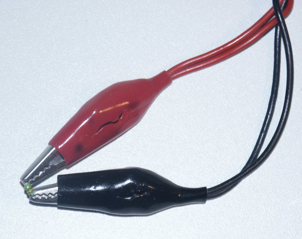
 2200 µF, 6.3 V Panasonic FM
All of the following examples are measured with an self made LCR-Adapter.
Unless otherwise noted all examples used an on board AMD HDA device, used an FFT size of 16384, took about one second and used
a noise pattern.
Note that while the 192 kHz of the HD Audio are particularly useful using 24 bit resolution typically adds no value. In
my case results were even worse. In fact all measurements are taken with only 16 bit. Up to 20 kHz almost any 16/48 sound
device would do the job as well.
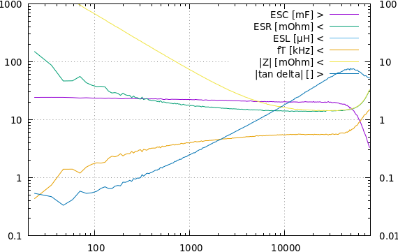
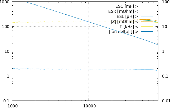
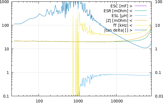
2200 µF, 6.3 V Panasonic FMThe ESR of this electrolytic capacitor is in the order of 12 mΩ. The raise of ESR at lower frequencies is typical for electrolytics.
The measurement is done with a reference of RRef = 200 mΩ.
The ESR at 120 Hz is by far better than the limit in the data sheet which allows tan δ up to 0.26, the actual value is about 0.06.
The deviations above 50 kHz are due to restrictions of the setup, especially the wiring.
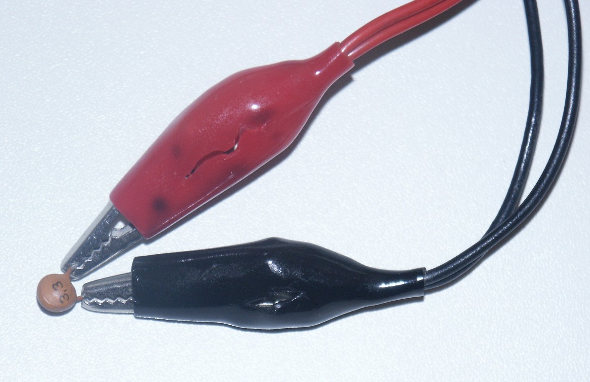 3.3
pF ceramic capacitor
3.3
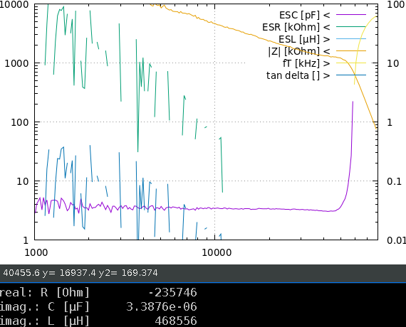
pF ceramic capacitorThe measurement is done with a reference of RRef = 20 kΩ.
This drive the impedance measurement to the limits. The capacity of the 3.3 pF capacitor is measured quite accurate. I really wonder that the measurement is still possible at a few kHz where reactance is beyond 10 MΩ, i.e. 3 orders of magnitude higher than the reference resistor.
Of course, ESR measurement is indeterminate. The values in the graph are just noise.
It is essential for this kind of measurement that the calibration is done with exactly the same wires. Again above 50 kHz the setup limits reasonable results.
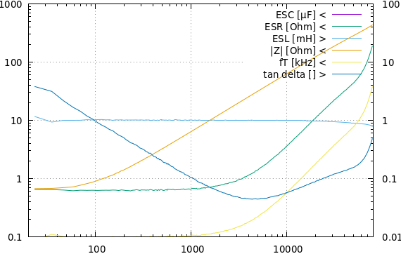
 10 µF, 16 V electrolytic
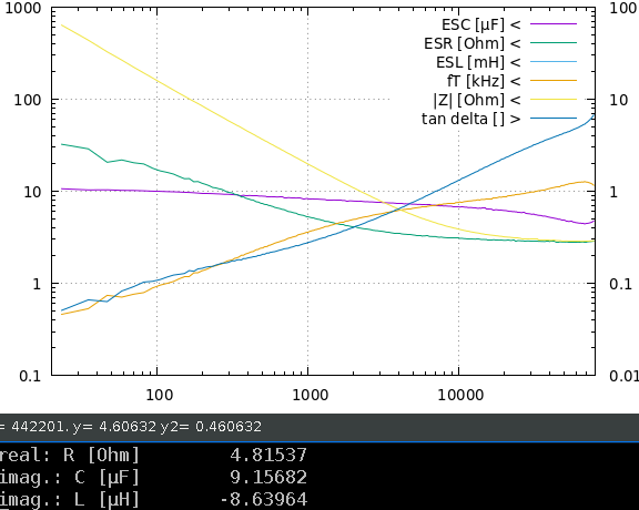
This is a "well done" used capacitor with poor performance but not yet defective.
The measurement is done with a reference of RRef = 20 Ω.
This capacitor provides the full capacity only at low frequencies. Above 10 kHz ESR dominates.
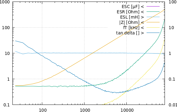
 1 mH air-core coil
This is an 1 mH coil for passive crossovers of loudspeakers.
The measurement is done with a reference of RRef = 20 Ω.
Noticeable the ESR grows above 1 kHz. This due to stray field dissipation.
 1 mH Ferrite core coil
This is also an 1 mH coil for passive crossovers but with a small Ferrite core.
Again the ESR grows above 1 kHz. But it is obvious that this component is superior to the allegedly superior air-core. The hysteresis loss is significantly less than the leakage field and the component is smaller, cheaper and has less DC resistance. (This is a vote not to use air-core coils for speaker crossovers.)
 220 nH
inductor
220 nH
inductorThis small 220 µH axial wired coil is measured with a reference of RRef = 200 mΩ.
The graph shows only about 200 µH. This is likely due to the restricted accuracy of the calibration with this reference. It is not that easy to get a low inductance high precision reference resistor in this range.
But beyond the limited absolute accuracy even a smaller inductor may be measured. Like with very small capacitors the result at lower frequencies is still sufficient for characterization.
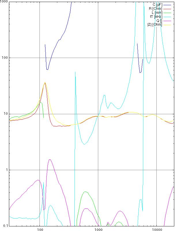 3 way loudspeaker
Complex impedance of an 8 Ω studio monitor satellite in a sealed enclosure with passive 3 way crossover.
Measured with an ALC650 on board audio device and a reference resistor of RRef = 20 Ω and
pink noise (weighted with f−0,5). FFT size is 65,536.
Most obvious is the resonance of the woofer at approx. 120 Hz. (An adequate frequency response is achieved by an Linkwitz Transformation filter in the active subwoofer crossover.)
The real ESR is about 0.5 Ω less because of the lack of a 4 point wire to the speaker. RDC is in real about 6.8 Ω.
 NiMH AA accumulator
This is the impedance of a Panasonic Infinium NiMH accumulator. The intrinsic resistance is about 22 mΩ which is typical for good NiMH AA cells.
The measurement is done with a reference of RRef = 200 mΩ. Additionally an offset voltage of 1 V is applied to avoid excessive discharge current during the measurement.
The ESL is probably due to wiring. It likely does not vanish below 1 kHz, it just cannot be measured with this equipment at lower frequencies.
This is the primary winding of a mains transformer, measured with a reference of RRef = 20 kΩ.
These measurements are done in sweep mode with a Panasonic WM61a measurement microphone and a small self-made microphone amplifier.
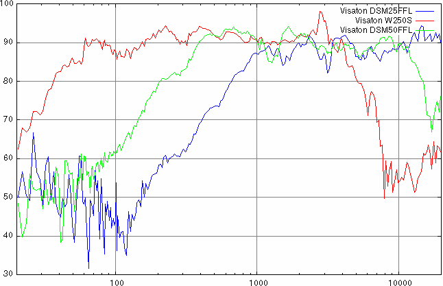 3 way loudspeaker
This is the raw response [dB SPL @ 2.83 V, 1 m] of a 3 way hi-fi speaker. The drivers are mounted in an 80 l vented enclosure and are measured without crossover.
Red graph: 10" woofer
Green graph: 2" dome mid range
Blue graph: 1" dome tweeter
The setup used the poor people's anechoic room: the garden with the speaker firing upwards. ;-)
The analysis uses the lock-in filter of Analyze that rejects noise to a very
high degree. So even a truck passing at the street cause no interference.
This measurement has also recorded the relative phase response (not shown). Together with an impedance measurement of each driver this is used to design the passive crossover with phase matching (everything else makes no much sense anyway).