Sound output of the Raspberry Pi
© 2014 Marcel Müller
Abstract:
There are many statements about the bad analog sound output of the
Raspberry Pi around. Most of them are predication rather than knowledge.
Let's come clean and add some facts!
Short answer: there are two things the Raspberry suffers from: enough bits
and a reasonable reconstruction filter. Everything else is OK for audio
playback.
There is a work around available for the reconstruction filter but not for
the limited resolution.
Topics: frequency response, signal
to noise, resampling, DC
offset, reconstruction filter, measurement
equipment, contact
Frequency response
and aliasing
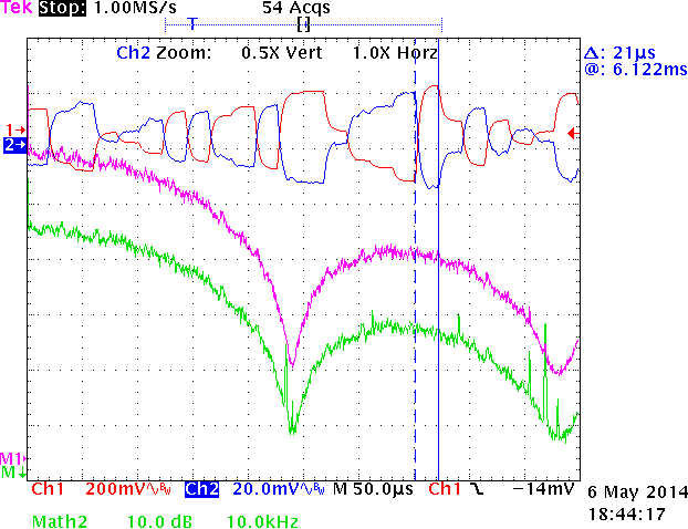
Fig. 1: frequency response of Raspberry Pi's analog sound output,
measured at 48 kHz sampling rate and white noise at -3 dB FSR for the
left channel and -23 dB FSR and inverted gain for the right one. The
FFTs are smoothed by a Blackman-Harris window function.
left channel, right
channel, FFT of left channel,
FFT of right channel
From the result to the right it is obvious that there is no
reconstruction filter behind the ADC except for a simple capacitator. The
48 kHz sampling rate of the DAC is clearly visible in the output. This
results in significant high frequency noise up to ≈ 80 kHz and
an amplitude drop of up to 5 dB at the Nyquist frequency (24
kHz). All frequency components above 24 kHz are mirrors of the audio
signal (aliasing).
Hopefully your audio equipment is not capable of reproducing all this
high frequency noise. It will drive your pets crazy and put unexpected
power to your tweeters. Fortunately most electrodynamic tweeters will have
higher impedance at these frequencies and so add some damping. But be
careful if you feed the output to a Piezo tweeter. This one has very low
impedance at high frequencies. Amplifiers usually dislike low impedance
together with output power (at the relevant frequencies).
See reconstruction filter for a way to
compensate for the high frequency noise and also the sinc degraded
response.
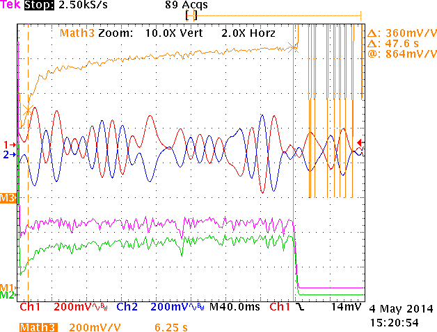
Fig. 2: frequency response of Raspberry Pi's analog sound output,
measured at 24 kHz sampling rate with 50 Hz bandwidth limited white
noise at -3 dB FSR. The right channel gets the inverted signal.
Additionally the right channel drives a load of 100 Ω while the left
channel is left at high impedance. The FFTs have a linear Y axis and are
smoothed by a Blackman-Harris window function. The M3 graph shows the
relative amplitude of right and left channel.
left channel, right
channel, FFT of left channel,
FFT of right channel, FFT
right / FFT left
Low frequency response and output impedance
There is no evidence of any significant high pass
filtering done by the sound output. The response is perfectly flat.
To show whether this also applies to lower impedance inputs I put a load
resistor of 100 Ω to the right channel only. Fig. 2 shows the effect. The
cut of frequency becomes ≈ 3 Hz which corresponds to a coupling capacitor
of 470 µF (most PC sound card have less). The output is obviously intended
to drive headphones directly.
Note: I had to reduce the sampling rate to 24
kHz (which does not impact this measurement) because the Raspberry's FFT
library cannot deal with more than 131,072 points.
Signal to noise and
distortion
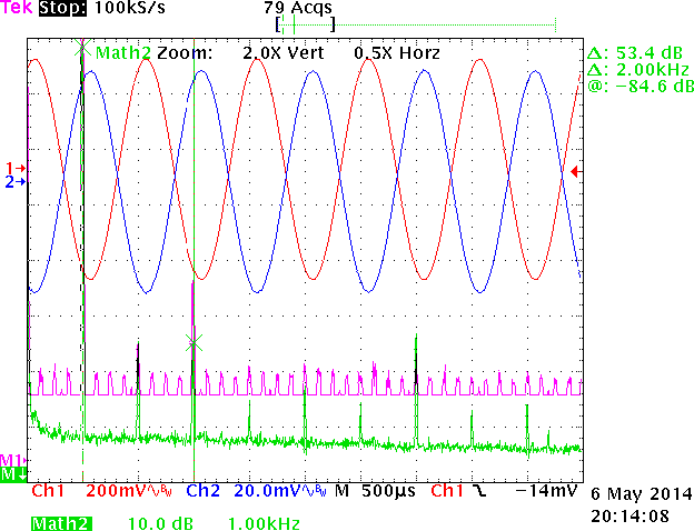
Fig. 3: frequency response of Raspberry Pi's analog sound output,
measured at 48 kHz sampling rate and 1 kHz sine wave signal at -3 dB
FSR. The right channel gets the inverted signal. The FFTs are smoothed
by a Blackman-Harris window function.
left channel, right
channel, FFT of left channel,
FFT of right channel
Note: the regular pattern at the floor of the left channel's
FFT with 250 Hz repetition has no special meaning. The amplitude is in
the order of 1 LSB in the internal representation. It is simply round
off noise during the FFT calculation in the scope that happened to have
some structure.
How linear is the output?
Fig. 3 pink graph shows the result when playing a 1 kHz sine wave. The
only significant distortion is the 3rd order harmonic (H3) at ≈
-53 dB.
Unlike other sound devices at low output levels the non linearity
increases (see green graph). It is quantization noise. But is
must be somehow asymmetric because of the even harmonics. Still the
amplitude is below -53 dB (of the reference signal) but for the 7th
order harmonics that is not that pretty. Practically it will be less when
using odd frequencies like 1.01 kHz which causes most of the harmonics
except for H2 to vanish. From the level of the distortion I would guess
that there are about 10 to 11 bits available for output. This is
in the order of the first generation CD players.
There is an interesting side effect of the way the Raspi's DAC works. If
you lower the sampling frequency of the 1 kHz test tone to 24 kHz the THD
decreases by about 6 dB. This is because of the fixed PWM frequency
(98 MHz) of the 1 bit DAC. Having a lower sampling rate the additional
time can be used to add another bit of resolution which results in 6 dB
less quantization noise.
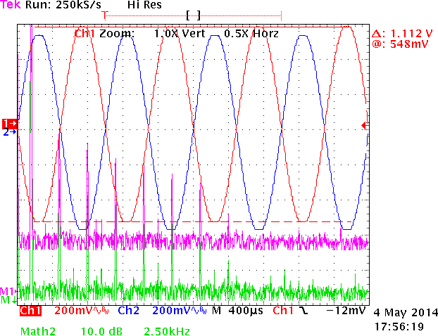
Fig. 4: frequency response of Raspberry Pi's analog sound output,
measured at 48 kHz sampling rate and 1 kHz sine wave signal at 0 dB FSR.
The right channel gets the inverted signal. The FFTs are smoothed by a
Blackman-Harris window function.
left channel, right
channel, FFT of left channel,
FFT of right channel
Overdriving
The situation changes dramatically if you raise the amplitude to 0
dB FSR. This causes the output to overdrive and odd
harmonics with significant level appear. The analog output is not capable
of driving the entire value domain of 16 bit samples. It saturates at ≈
1,1 VSS.
This is a bad news because many pop songs are normalized to 0 dB FSR you
will like run into this pitfall. 0 dB FSR is a bad idea for other reasons
(see loudness war)
but it is reality. However, taking back the volume by only 1 dB solves the
problem. There is no significant distortion at -1 dB FSR.
Resampling
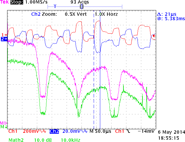
Fig. 5: frequency response of Raspberry Pi's analog sound output,
measured at 44.1 kHz sampling rate and white noise at -3 dB FSR for the
left channel and -23 dB FSR inverted for the right one. The FFTs are
smoothed by a Blackman-Harris window function.
left channel, right
channel, FFT of left channel,
FFT of right channel
Most audio material around is sampled at 44.1 kHz rather than 48 kHz. So
what about 44.1 kHz playback?
Obviously the playback of the RPI is always at 48 kHz and the resampling
is done in software. Probably the video core does the job because I can't
see any significant CPU load (in contrast to software resampling by the
PulseAudio daemon).
The good news is that the used resampling algorithm does it's job
quite well - better than the following 48 kHz DAC by far. The low
pass filter starts at 18 kHz and drops almost to zero at 22 kHz. The
cut-off frequency is about 19 kHz. That's OK for audio playback.
Now the bad news: I don't know any reason why the Raspberry cannot play
44.1 kHz natively.
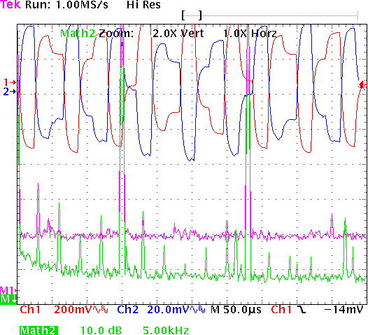
Fig. 6: frequency response of Raspberry Pi's analog sound output,
measured at 44.1 kHz sampling rate and 15 kHz sine wave signal at -3 dB
FSR for the left channel and -23 dB FSR inverted for the right one. The
FFTs are smoothed by a Blackman-Harris window function.
left channel, right
channel, FFT of left channel,
FFT of right channel
And what about resampling artifacts?
Well, there are some. But don't worry, you will survive them. The 15 kHz
test signal in Fig. 4 has an aliasing frequency at ≈ 3 kHz. At lower
amplitude quantization noise comes into play as already mentioned above.
DC offset
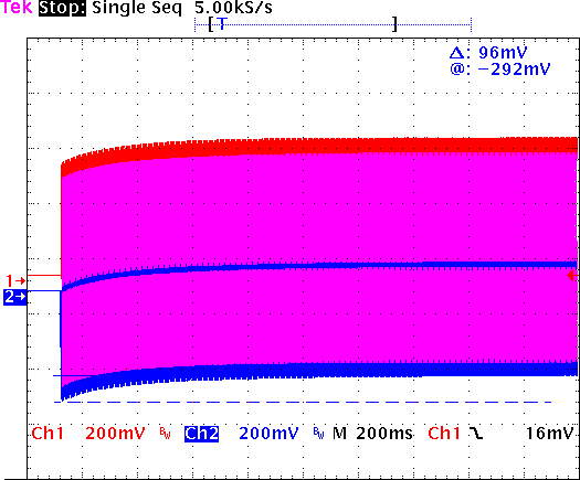
Fig. 7: startup of playback of 50 Hz sine wave at Raspberry Pi's analog
sound output, measured at 48 kHz sampling rate at -3 dB FSR: left
channel, right channel
The Raspberry Pi has a DC offset at the output. Normally this is
compensated by decoupling capacitors. However, the bias vanishes when
playback has completely stopped. This caused popping sounds. Newer
firmware compensate for that by slowly changing the bias to move the
frequencies into the subsonic range of 5 Hz and less. Although this is a
hack, it works as expected. You wont hear anything on start of playback.
You simply shouldn't care about this topic.
Fig. 7 shows how the offset built up after start of playback. After about
1 second everything is done.
Cross talk and symmetry
I got no indication that either cross talk or differences between the
left and the right channel are relevant in any way.
Build a reconstruction filter
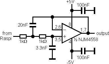
Fig. 8: reconstruction filter for analog output of Raspberry Pi.
The missing reconstruction filter can be added externally with reasonable
effort. The circuit in fig. 8 will provide the missing filter. It is a
second order Sallen-Key
filter with f0 = 19.6 kHz and Q = 1.23. It has been
optimized exactly for the Raspberry Pi not for any other device. Beside
the compensation for the sinc function it also takes care of the built-in
low-pass with 3 µs time constant.
- You need two instances of the circuit. One for the left channel and
one for the right.
- One NJM4558 is sufficient as it contains two operational amplifiers.
Other 4558 clones like RC4558 (RCA), LM4558 (National/TI) will do their
job as well but the NJM4558 from New Japan Radio is one of the cheapest.
But avoid very simple opamps like LM358. If you need to drive headphones
directly replace the chip by the power opamp NJM4556, but I don't
recommend that because the sound quality of the Raspberry is not
sufficient for headphones.
- Be sure to use low tolerance capacitors for the filter, i.e.
the 3,3 nF and the 20 nF. 5 % tolerance should be fine. If you can't get
20 nF use two with 10 nF in parallel.
- The circuit need a negative supply voltage. The Raspberry Pi
only has positive supply. So you need either some power supply that
provides negative voltages as well or use a voltage inverter that
converts the +5 V from the Raspi to -5 V. Simple charge pump converters
like LTC1046 or MAX829 are sufficient. Usually they have a bit less
output. That don't care, -4 V is just as fine.
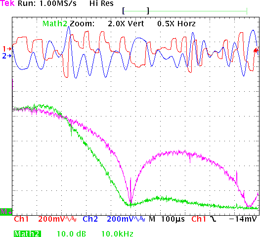
Fig. 9: frequency response of Raspberry Pi's analog sound output with
(right channel) and without (left channel) external reconstruction
filter, measured at 48 kHz sampling rate with white noise at -3 dB FSR.
The right channel is inverted. The FFTs are smoothed by a
Blackman-Harris window function.
left channel, right
channel, FFT of left channel,
FFT of right channel
Result
The filter is by far not perfect but it significantly improves the
frequency response. Up to 20 kHz the response is closer to linear and
above 20 kHz high frequency noise is reduced. Even in the time domain any
visible steps have vanished. There is a slight overshoot at the resonance
around 13 kHz and also some group delay. But no problem, you won't hear
either of them.
For sure an elliptical filter would perform better but they are difficult
to build and hey, it's a Raspberry not Harman Kardon.
Measurement equipment
All measurements are done with a Tectronix TDS 754A digital
oscilloscope. The test signal are generated by this
software on the fly. Calculations are done with Mathematica.
If you have remarks or complaints (not too much, of course ;) feel free
to contact me: