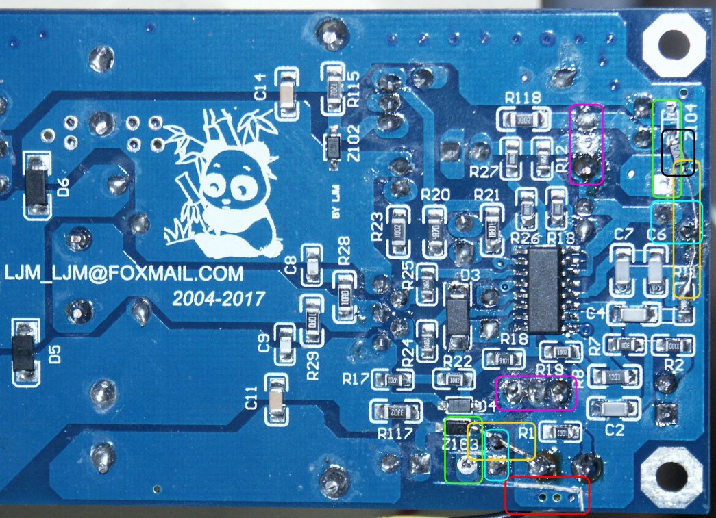
Bottom side of modified L15D module.
For simple applications there are cheap Class D modules based on Infineon IRS2092 sold as "L15D". These modules perform quite well, but depending on your needs there may be further improvements.
The IRS2092 provides a floating input. Unfortunately the L15D modules do not expose this feature.
However, the ground planes of the input and the power part are almost separated. But they are connected at one place. So it is possible to disconnect input ground and power ground. Unfortunately two capacitors and two Zener diodes are connected to the wrong ground plane (green markers). So you have to rewire them to the right one if you want to separate the ground planes.
Cut the ground planes (red marker). The 3 vias are the only connection between AGND and power GND.
Remove electrolytics CP9 and CP10.
Drill new holes for the GND pins of CP9 and CP10 (center of yellow markers).
Reinsert CP9 and CP10 using the new holes instead of the old GND connections (cyan markers). Solder them at one side.
Remove Z104 and rotate it around their anode (black marker).
Cut GND connection of Z103 (center of lower green marker).
Create wire from anode of Z103 to CP10 and to AGND (left yellow marker).
Create wire from cathode of Z104 to CP9 and AGND at R11 (upper right yellow marker).
Now you are done, analog ground is now separated from power ground. Ensure that the two ground planes do not become a significant level difference. A few Volts are no problem, but the power supply of the input part comes still from the main supply. In fact - input and power GND should be connected somewhere else.
Note that you only need step 1 if you use an external power supply like below.
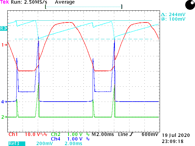
The switching frequency is approximately 300 kHz. The output has a significant ripple at this frequency. While this will not harm dynamic speakers you may dislike the electromagnetic noise if you have longer wires connected.
You can decrease the noise by an increased output capacitor at the cost of lower high frequency response. Remember to use X-capacitors only that can deal with the constant ripple current.
The L15D module is designed to drive 4 Ω speakers. If you drive 8 Ω speakers there is an overshoot at the high frequency response. Increasing the output capacity will compensate for that. You should add approximately 330 nF in this case.
If your amplifier drives a sub woofer the high frequency response can be ignored and you can safely add 2,2 µF parallel to the load. This significantly reduces output ripple.
The power supply for the input part of the IRS2092 is taken from the main power supply by linear regulators. They consume roughly half of the idle power of the module. You can save approximately 1 W with an alternate power supply. This becomes more important if you need further power e.g. for active crossovers.
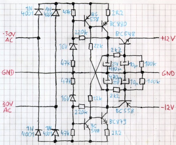
This solution provides up to ±30 mA, enough for the IRS2092 and a few operational amplifiers. The power
consumption is significantly lower than a linear regulator.
It is some kind of synchronous rectifier that opens only when the instantaneous voltage is close to the target voltage. This
keeps the power dissipation low. A small linear regulator at the output removes the residual ripple.
The circuit is short-circuit proof. It simply provides only a limited power. This also causes a soft start.
The AC voltage need not exactly to fit the 30 V AC. Any AC voltage suitable to supply the L15D module should be fine. Lower input voltage generally increases the maximum output current. Increase the 2,2 Ω emitter resistors to compensate for that if you have significantly less input.
Feel free to use different transistor types. Only ensure that the shorted emitter of the Darlington does not impact hfe at low currents too much.
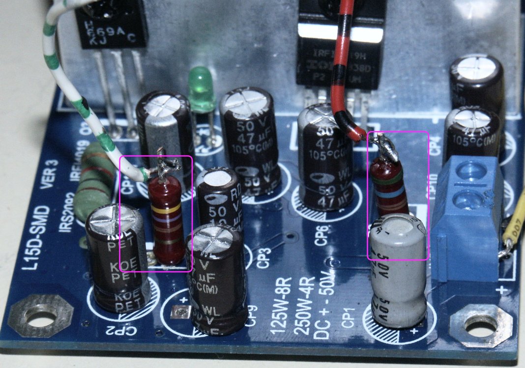
To use the alternate power supply for the L15D module do the following changes:
Remove the TO220 transistors Q1 and Q2 (pink marker).
Insert a resistor with about 500 Ω into the emitter pin of the transistors. The power consumption is slightly asymmetric. So I used 470 Ω and 560 Ω.
Wire the upside of the resistors to the output of the power supply.
You do not need the modifications for the ground plane split except for step 1 if you do this modification. Strictly speaking you could remove CP9, CP10, Z103 and Z104 too, but this makes no significant difference.